Mon/Sat 9.00am to 7.00pm


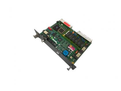
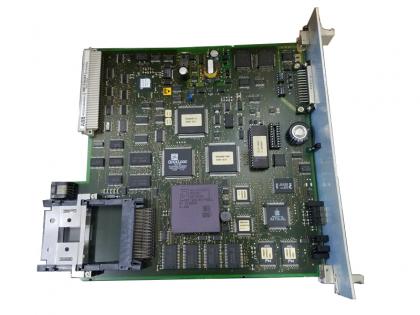
GE IS200ERBPG1A EX2100 series Regulator M1 Backplane

GE IS200ERBPG1A EX2100 series Regulator M1 Backplane
Brand:
General Electric PLCItem NO.:
IS200ERBPG1ACAOrder(MOQ):
1 PCPayment:
T/TMarket Price:
999Price Range:
1 - 5Product Origin:
USAColor:
Depends on materialShipping Port:
XIAMENLead Time:
IN STOCKWarranty:
1 year
GE IS200ERBPG1A EX2100 series Regulator M1 Backplane
Description:
The exciter is a flexible modular system that can be assembled to provide a range of available output currents and several levels of system redundancy. These options include power from a potential, compound, or auxiliary source. Single or multiple bridges, warm backup bridges, and simplex or redundant controls are available.
Power for the exciter is drawn from a power potential transformer connected to the generator terminals, or from an excitation transformer connected to an auxiliary bus.
Generator line current and stator output voltage are the primary feedbacks to the exciter, and dc voltage and current is the controlled output to the exciter field. The architecture supports Ethernet LAN (Unit Data Highway) communication with other GE equipment including the GE Control System Toolbox (toolbox) forconfiguration, the turbine control, the LCI Static Starter, and the HMI (operator interface). In the potential source system, the secondary of the PPT is connected to the input of a 3-phase full-wave inverting thyristor bridge.
The inverting bridge provides both positive and negative forcing voltage for optimum performance. Negative forcing provides fast response for load rejection and de-excitation. Either simplex or redundant control is available. Excitation control results from phase controlling the output of the SCR bridge circuit. The SCR firing signals are generated by digital regulators in the controller. In the redundant control option (Figure 1-2), either M1 or M2 can be the active The exciter is a flexible modular system that can be assembled to provide a range of available output currents and several levels of system redundancy. These options include power from a potential, compound, or auxiliary source. Single or multiple bridges, warm backup bridges, and simplex or redundant controls are available.
Power for the exciter is drawn from a power potential transformer connected to the generator terminals, or from an excitation transformer connected to an auxiliary bus. Generator line current and stator output voltage are the primary feedbacks to the exciter, and dc voltage and current is the controlled output to the exciter field.
The architecture supports Ethernet LAN (Unit Data Highway) communication with other GE equipment including the GE Control System Toolbox (toolbox) for
configuration, the turbine control, the LCI Static Starter, and the HMI (operator interface).
In the potential source system, the secondary of the PPT is connected to the input of a 3-phase full-wave inverting thyristor bridge. The inverting bridge provides both positive and negative forcing voltage for optimum performance. Negative forcing provides fast response for load rejection and de-excitation. Either simplex or redundant control is available.
Excitation control results from phase controlling the output of the SCR bridge circuit. The SCR firing signals are generated by digital regulators in the controller. In the redundant control option (Figure 1-2), either M1 or M2 can be the active master control, while C monitors both to determine which should be the active and which the standby controller. Dual independent firing circuits and automatic tracking is used to ensure a smooth transfer to the standby controller. master control, while C monitors both to determine which should be the active and which the standby controller. Dual independent firing circuits and automatic tracking is used to ensure a smooth transfer to the standby controller.